Thoughts on the Collapsed Spine
One of the designs I’ve been encountering a lot of recently is a “collapsed spine” data center network, as shown in the illustration below.
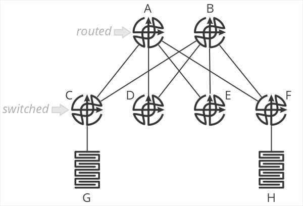
In this design, and B are spine routers, while C-F are top of rack switches. The terminology is important here, because C-F are just switches—they don’t route packets. When G sends a packet to H, the packet is switched by C to A, which then routes the packet towards F, which then switches the packet towards H. C and F do not perform an IP lookup, just a MAC address lookup. A and B are responsible for setting the correct next hop MAC address to forward packets through F to H.
What are the positive aspects of this design? Primarily that all processing is handled on the two spine routers—the top of rack switches don’t need to keep any sort of routing table, nor do any IP lookups. This means you can use very inexpensive devices for your ToR. In brownfield deployments, so long as the existing ToR devices can switch based on MAC addresses, existing hardware can be used.
This design also centralizes almost all aspects of network configuration and management on the spine routers. There is little (if anything) configured on the ToR devices.
What about negative aspects? After all, if you haven’t found the tradeoffs, you haven’t looked hard enough. What are they here?
First, I’m struggling to call this a “fabric” at all—it’s more of a mash-up between a traditional two-layer hierarchical design with a routed core and switched access. Two of the points behind a fabric are the fabric doesn’t have any intelligence (all ports are undifferentiated Ethernet) and all the devices in the fabric are the same.
I suppose you could say the topology itself makes it more “fabric-like” than “network-like,” but we’re squinting a bit either way.
The second downside of this design is that it impacts the scaling properties of the fabric. This design assumes you’ll have larger/more intelligent devices in the spine, and smaller/less intelligent devices in the ToR. One of my consistent goals in designing fabrics has always been to push as close to single-sku as possible—use the same device in every position in the fabric. This greatly simplifies instrumentation, troubleshooting, and supply chain management.
One of the primary points of moving from a network in the more traditional sense to a “true fabric” is to radically simplify the network—this design doesn’t seem like it’s as “simple,” on the network side of things, as it could be. Again, something of a “mash-up” of a simpler fabric and a more traditional two-layer hierarchical routed/switched network.
Scale-out is problematic in this design, as well. You’d need to continue pushing cheap/low-intelligence switches along the edge, and adding larger devices in the spine to make this work over time. At some point, say when you have eight or sixteen spines, you’d be managing just as much configuration—and configuration that’s necessarily more complex because you’re essentially managing remote ports rather than local ones—as you would by just moving routing down to the ToR devices. There’s some scale point here with this design where it’s adding overhead and unnecessary complexity to save a bit of money on ToR switches.
When making the choice between OPEX and CAPEX, we should all know which one to pick.
Where would I use this kind of design? Probably in a smaller network (small enough not to use chassis devices in the spine) which will never need to be scaled out. I might use it as a transition mechanism to a full fabric at some point in the future, but I would want a well-designed planned to transition—and I would want it written in stone that this would not be scaled in the future beyond a specific point.
There’s nothing more permanent in the world than temporary government programs and temporary network designs.
If anyone has other thoughts on this design, please leave them in the comments below.
It works on paper, sure. But consider a few real-world problems with this:
1. For flows from G, which uplink does C use? Remember, it’s only a layer-2 switch so ECMP can’t be used. The uplink needs to be a layer-2 VLAN, the first-hop is probably a VRRP gateway provided by A and B over the uplink VLAN so only 1 link will be in use at any time. C could use LACP if A and B supported multi-chassis aggregation, but that makes A and B different devices from simple routers.
2. There’s no layer-2 between leafs. Now you can tell the VMware guys they just can’t do their vmotions between leafs – but that won’t last long. Consider if you need to add a firewall: it’s connected to a leaf, and the security guys won’t allow a layer-3 router between hosts and the firewall – because, well, routers can leak traffic away from the firewall.
In the end, A and B are better off being a multi-chassis switch capable of MC-LAG to each leaf and providing layer-2 between leafs. Then provision layer-3 VRFs into VLANs as required. I think in the real world that’s about as close to this model as you’ll be able to get.
I would assume ESI-LAG is used in the example? Or is it as Kerry is saying that a VLAN cannot span multiple access switches?
We have been using an ESI-LAG design in some locations for about 3 years now and are quite happy with it. We’re running QFX10k in core with EX4300 VC’s at the access. The 4300 can be replaced by anything that does LACP basically. Firewalls connect directly to the core and there’s a BGP session to the FW where we rewrite the next-hop to the VirtualGatewayAddress for quick failover. When we reboot one of the core routers for an upgrade clients don’t even notice it which is very nice.
The biggest downside I would say is Scalability, East-West traffic always has to go back to the core and there is no routing at the edge.
As for cost of the core routers (spines?). You could do this with 2x QFX5120 or 7050X3 which aren’t too expensive. But again, scale is limited.
[…] White shares some thoughts on the collapsed spine network […]